A little while ago, ON4AOL (Luc) forwarded me a link to an article by Daniel Estévez (EA4GPZ/M0HXM), ORI’s lunar descent CTF, with the simple question of whether this might be something for me.
Curious about what it was actually about, I read the article and immediately followed a few threads of my own, all the way down to the source code of the puzzle itself on GitHub. What follows is my attempt to describe, in plain language, what it is about and why I think this is worth a look for us as radio amateurs too. There is a glossary at the bottom for any word that is not immediately clear while reading.
Here is the puzzle in one sentence:
Imagine you are handed the complete software of a lunar lander, and you know that this lander keeps crashing. The radar that measures altitude works perfectly. Yet the craft crashes every single time, right before touchdown. Why?
A perfect altimeter, a guaranteed crash. The whole answer hides in one number: the velocity.
An unusual kind of Capture The Flag
This is the puzzle that the Open Research Institute (ORI), an American non-profit that develops open-source technology for spaceflight and radio amateurs, put in front of visitors at BSides San Diego 2026, a security and hacker conference. It is a so-called CTF, short for Capture The Flag: a puzzle contest where you earn “flags” (code words, points) step by step by solving a technical problem. This CTF is not about classic computer hacking, but about radar and signal processing. That is exactly what makes it so recognisable for radio amateurs.
The setting: Chandrayaan-3 and the KaRA radar
The puzzle is not a fantasy story. It is based on real, existing technology. Chandrayaan-3 was the third Indian lunar mission of the Indian space organisation ISRO. On 23 August 2023, the lander of that mission, Vikram, became the first ever to make a soft landing near the south pole of the Moon. With that, India became the fourth country ever to land softly on the Moon.
To know how high it was still hovering above the ground and how fast it was approaching, Vikram used an instrument called KaRA: the Ka-band Radar Altimeter.
According to the documentation for this CTF, the real KaRA processing software ran on a single Xilinx Virtex-5 FPGA, a kind of reprogrammable chip.
The CTF is a Python re-creation of that KaRA radar, based on a scientific publication about the real design (Sharma et al., IEEE Aerospace and Electronic Systems Magazine, January 2026). That simulation in turn drives a rebuilt autopilot, which has to decide how the lander corrects its course. You get to see all of the code, so there is no hidden secret in a chip. You simply have to understand the logic.
Three test flights
The puzzle tests your solution against three different descent profiles.
- The first profile, “standard”, is a calm, steady descent from 10 kilometres down to just above the ground, roughly like the one Chandrayaan-3 flew.
- The second, “aggressive”, is a fast, braking descent that goes from 10 kilometres to 3 metres in under seven minutes.
- The third, “stepwise”, lets the lander hover for a while at a series of fixed altitudes and then drop quickly to the next one. This happens deliberately at exactly the altitudes where the radar has to switch measurement setting, to stress the system a little extra.
Without any modification, the lander crashes in all three cases. The altitude measurement itself is correct down to the last metre. The problem lies somewhere else.
How does a radar like this measure altitude, and what is a chirp?
Compare the radar to a bat flying with echolocation: it sends out a sound signal and listens for the reflection. How long it takes for the echo to come back tells it how far away an object is.
KaRA does something similar, but with radio waves. Instead of sending one fixed tone, the radar sends a chirp: a signal whose frequency slides evenly from low to high within a short, fixed span of time. The name comes from the bird sound that does the same thing, a short tone that quickly changes pitch, like a bird chirping.
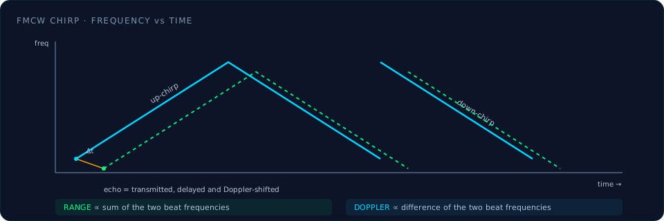
The clever thing about such a chirp is that, by comparing the reflected signal with what you just transmitted yourself, you can derive two things at once:
- the distance to the ground,
- and the speed at which you are approaching, via the Doppler effect.
That is the same effect that makes an ambulance siren sound higher as it approaches and lower once it drives away. To cleanly separate distance and speed, the radar sends two chirps one after another each time: an “up-chirp” whose frequency rises, and a “down-chirp” whose frequency falls.
The reflected signal is digitised and then run through a mathematical operation called an FFT, short for Fast Fourier Transform.
The 13 measurement modes, and why measuring briefly is less accurate
How long a chirp may last depends on how high the lander is flying. High above the ground a chirp may last a long time, almost a tenth of a second, but just above the ground it has to be lightning fast, barely one and a half microseconds, otherwise the echo is already back before the radar has finished transmitting. That is why the radar has 13 fixed measurement modes, each with its own chirp duration, suited to a different altitude range. A few examples from the table the CTF code can print itself with the command python lunar_descent_ctf.py --modes:
| Mode | Chirp duration | Valid altitude range | Accuracy (m/bin) | Real measurements (of 8192) |
|---|---|---|---|---|
| 0 | 1.45 µs | 1.7 to 3.6 m | 0.00057 m | 14 |
| 2 | 6.12 µs | 7.3 to 15.3 m | 0.0024 m | 63 |
| 6 | 109 µs | 129 to 272 m | 0.043 m | 1127 |
| 9 | 946 µs | 1122 to 2362 m | 0.37 m | 8192 (full) |
| 12 | 8.2 ms | 9731 to 20486 m | 3.23 m | 8192 (full) |
The key things to remember:
- The FFT always expects 8192 samples.
- At the high modes, 9 through 12, the chirp actually delivers that. But at the low modes, just above the ground, where it matters most, the chirp delivers only a handful of real samples, 14 in the worst case, and the rest of the 8192 bins are simply filled with zeros.
- That filling with zeros, called “zero padding”, is technically fine for still being able to run an FFT, but it makes the peak in the FFT broad and fuzzy instead of sharp. And a broad, fuzzy peak is hard to pin down precisely.
The problem: altitude is right, velocity is not
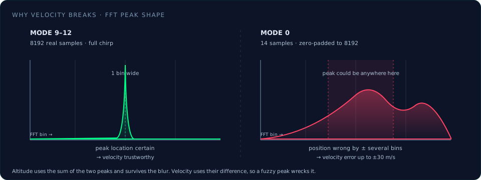
Here is the heart of the matter:
- For the altitude measurement, which is computed from the sum of the up-chirp and down-chirp peaks, that width of the peak barely matters: by a lucky coincidence two error sources cancel each other out, regardless of the mode.
- But for the velocity measurement, computed from the difference between the two peaks, a broad, imprecise peak is a real problem. At the shortest chirp, mode 0 with only 14 real samples, the velocity error can run up to several tens of metres per second: completely unusable. And that is precisely at the moment when the lander is hovering just above the ground and needs to rely on a correct speed the most.
This is literally visible in the simulation output from the original article. A fragment, with time in seconds, altitude in metres and velocity in metres per second:
| Time | True Alt | RAP Alt | True Vel | RAP Vel | Mode |
|---|---|---|---|---|---|
| 100.0 | 4000.0 | 3999.7 | 33.3 | 34.5 | 10 |
| 577.2 | 4.4 | 4.4 | 0.4 | 15.9 | 1 |
| 578.9 | 3.7 | 3.7 | 0.4 | -5.3 | 1 |
“True” is the actual value the simulation takes as its starting point, “RAP” is what the radar processing (Radar Altimeter Processor) roughly measures out of it.
- At 4 kilometres altitude, in mode 10 with many samples, the actual and measured speed are still nicely close: 33.3 against 34.5 m/s.
- But just above the ground, in mode 1 with few samples, the measured speed jumps from 15.9 to -5.3 m/s, while the actual speed stays calmly around 0.4 m/s.
- That is pure noise, not a real measurement. The altitude measurement in that same fragment stays accurate to within a few centimetres.
That is exactly the problem that needs solving.
What decides what the pilot sees: the MeasurementQualifier
The raw radar measurements do not go straight to the autopilot. They first pass through a piece of software that decides which measurements are reliable enough: the MeasurementQualifier. This is the only place in the whole CTF code that you, as a participant, are allowed to change. Everything outside it, the radar simulation, the autopilot, the scoring, is off limits.
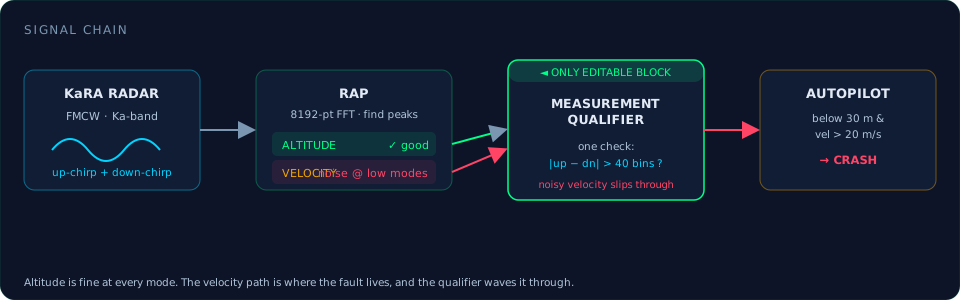
To be sure how that starting code looks exactly, I pulled it straight from the official GitHub repository. It is indeed very simple, exactly as the article describes:
- there is only one check. If the difference between the up-chirp and down-chirp peaks, expressed in FFT bins, is larger than a fixed threshold of 40 bins (about 50 kHz), the measurement is rejected.
- If the difference stays under that threshold, the measurement, altitude and velocity both, passes through to the pilot without any further questions.
And that is where the problem sits. At the shortest mode, with 14 real measurements, the measured speed can deviate by tens of metres per second from reality, without the difference between the two peaks becoming large enough to cross that fixed threshold of 40 bins.
So for this simple check the measurement looks valid, while the value internally is mostly noise. That noise then passes unfiltered to the autopilot. Just above the ground it sees a nonsensically high speed, thinks it is drifting sideways and needs to correct, gives full sideways thrust because of that, and precisely because of that it tips over. That is how the crash happens.
The puzzle and the flags
Participants could earn three flags, together worth 1000 points.
Total 1000 points · unmodified code scores 0 / 1000
The lander crashes guaranteed, in all three scenarios.
How was it solved? Two levels
After the event was over, ORI released two example solutions, which nicely show how you first solve a problem coarsely, and only then finely.
- The first, simple fix (good for flag 2, 500 points) simply throws away the velocity measurement as soon as a measurement comes from a mode with fewer than 100 real samples, and uses 0 m/s instead. The altitude measurement stays in use. This is actually a bit of cheating: it does not really solve the underlying problem, it only hides it. Still, this is already enough to land all three scenarios safely, because just above the ground the lander has hardly any speed left anyway. A crude assumption that happens to be right most of the time.
- The second, full fix (good for flag 2 and flag 3, 900 points) does two things more cleverly.
- First, the threshold above which a velocity difference is rejected as “too large to be true” is adjusted per mode: for modes with many samples, high above the ground, where high speeds are normal and reliable, the threshold may be generous; for modes with few samples it has to be strict.
- Next, instead of simply filling in 0 on an unreliable measurement, the system holds on to the last known good velocity: a kind of educated guess based on what you already knew, a very simple cousin of the Kalman filter covered further on, with just one remembered value instead of a full probability distribution. That way the system never again wrongly rejects a valid measurement (flag 3), while the speed estimate still stays reasonably right.
And what did Daniel Estévez himself do?
In his article, Estévez goes a step further than these two official solutions. What is interesting is not only what he built, but also how he worked towards it step by step.
- He started by cloning the repository and immediately deleting the folder with the ready-made solutions, to force himself to tackle the puzzle without help. His first step was simply to read the code thoroughly. The first flag of the CTF is earned by explaining to the organisers what is wrong, and that answer turned out to be largely present already in a comment in the code itself. So that first step was mostly a reading exercise for him: understanding well what happens before changing anything at all.
- Once he realised that the problem was with the velocity measurement on the low modes, his first impulse was to make the radar processing itself smarter, for example with a better method to locate the peak in the FFT. He had to drop that idea right away, because that code belonged to the forbidden territory of the puzzle: only the measurement qualification was allowed to be changed.
- Next he noticed that a shortcut was possible. Because the puzzle only checks whether the passed velocity is not too large, he could simply return a zero value on the lowest modes and get the full score that way. He calls that a form of cheating himself: it brings in the points, but does not really solve the problem behind it.
- That is why he chose to tackle it properly after all, with a Kalman filter, even though it was not needed to score. To make that filter work well, he had to break one small rule of the puzzle: he added a time parameter to a function that was not supposed to be modified, because the filter needs to know how much time has passed between two measurements, and that differs per test scenario.
- For building the filter itself he fell back on the standard formulas you find on Wikipedia for a Kalman filter, with altitude and velocity as the two quantities he was trying to estimate.
- For the two uncertainty parameters such a filter needs, he chose himself, based on engineering insight rather than an exact calculation: how strongly he expected the state of the lander to change from moment to moment, and how uncertain he rated a radar measurement depending on the mode used.
- Finally he tested his solution thoroughly. He modified the code to print all intermediate steps instead of only some, added extra columns to lay true and estimated values side by side more easily, and turned the simulation loose on all test scenarios. That way he could see for himself where his filter worked well, and where it had to catch up for a moment, such as at a sudden altitude jump.
That work paid off. In his simulations the estimated altitude and velocity tracked the true values to within a metre and to less than a metre per second. Over a whole descent from 10 kilometres down to the ground, the final position error stayed only about 17 metres. Even at that sudden altitude jump in the “standard” scenario, from 3 to 20 metres at the 600 second mark, when the radar briefly produces no valid measurement at all, the filter recovered smoothly as soon as a measurement came in again.
Estévez underlines a point that comes straight from engineering practice: the easy solution, simply ignoring the velocity when it is wrong, gets the full score in this game, but is technically unsatisfying. A slightly harder approach, where you really learn to deal with uncertain sensor data, as with a well-tuned Kalman filter, delivers a far more usable and realistic result, exactly the way it is done in real spaceflight engineering too.
What I found in the code
While reading through the source code, there are a few more things that can be found directly in the official code, and that are worth mentioning even though they are not stated so explicitly in the article.
- The autopilot crashes specifically when the reported altitude drops below 30 metres AND the reported velocity exceeds 20 m/s. Above 30 metres the speed may well be high, that is part of a fast descent, and only just above the ground does it become dangerous. According to the comment in the code, on a wrong velocity measurement the pilot thinks it is drifting sideways, therefore gives full sideways thrust, and the lander tips over because of it.
- The three test profiles are also defined more precisely than the article shows. The “stepwise” profile, which combines hovering with fast jumps, turns out to hover specifically at the altitudes where the radar has to switch mode: 9851, 4795, 2334, 553, 131, 31 and 5 metres, each time hovering for 85 percent of a segment, followed by 15 percent of quickly dropping to the next altitude.
- Furthermore, the repository turns out to contain a second, separate Python file,
kara_rap_reference.py, that is not used by the actual CTF code. It is a more extensive, more faithful re-creation of the full KaRA system from the scientific publication, including things like automatic gain control that were left out of the CTF itself. This file apparently serves as a piece of evidence that the underlying physical model of the CTF matches the publication, separate from the puzzle itself. - Finally, the code itself also gives hints if you score low. At a score of 0, for example, the tip appears: “The altitude readings are fine. Look at the velocity. How many signal samples does mode 0 have?” A small nudge in the right direction for anyone who is stuck.
Why this is interesting for us too
This puzzle revolves around a question that shows up everywhere in radio technology, far beyond spaceflight: when do you trust a measurement, and when do you not? That same trade-off plays out in weather radars, in automotive radars for adaptive cruise control, in GPS receivers that have to judge whether the satellite geometry is good enough to rely on, and in every homebrew project where you try to measure a weak or noisy signal. FMCW radar itself, with chirps, FFTs and bins, is moreover technology that a radio amateur may well encounter one day when experimenting with radar or Doppler measurements, even though we ourselves usually sit on much lower frequencies than the Ka-band.
For me this was a good reminder that a lot of what happens inside a spacecraft altimeter is the same signal processing we meet on the workbench, just at a different frequency and with the stakes turned all the way up.
73, Kristof, ON3VZ
Glossary
| Term | Explanation |
|---|---|
| CTF (Capture The Flag) | A puzzle contest where participants solve technical problems to earn code words (“flags”). |
| FMCW radar | Frequency-Modulated Continuous Wave: a radar that transmits continuously while the frequency of the signal changes gradually. |
| Chirp | A radio signal whose frequency rises or falls evenly during a short, fixed period, similar to a bird chirping. |
| Ka-band | A part of the radio spectrum between roughly 26.5 and 40 GHz, much higher than the common amateur radio bands. |
| KaRA | Ka-band Radar Altimeter, the radar altimeter carried aboard the Chandrayaan-3 lander. |
| RAP | Radar Altimeter Processor, the part that turns the raw radar measurements into altitude and velocity values. |
| FFT (Fast Fourier Transform) | A mathematical operation that breaks a signal down into the frequencies it is built from. |
| Bin | One of the small frequency slots into which an FFT divides a signal. |
| Zero padding | Filling a measurement series that is too short with zeros, so that an FFT of fixed length can still be run on it. |
| Doppler effect | The shift in frequency of a wave when the source and the observer move relative to each other, used to measure speed. |
| Mode (sweep mode) | One of the thirteen preset combinations of chirp duration and measurement range that the radar uses, depending on altitude. |
| Kalman filter | A mathematical method to combine a new, uncertain measurement with a prediction based on earlier data, into a more reliable estimate. |
| MeasurementQualifier | The part of the CTF code that decides which radar measurements are reliable enough to pass to the autopilot. |
| ISRO | The Indian space organisation (Indian Space Research Organisation). |
| Vikram | The name of the lander of the Chandrayaan-3 mission. |
Sources
- Daniel Estévez (EA4GPZ/M0HXM), ORI’s lunar descent CTF, destevez.net, July 2026: destevez.net/2026/07/oris-lunar-descent-ctf
- Open Research Institute, OpenResearchInstitute/lunar-descent-ctf (source code, README and official solutions), GitHub: github.com/OpenResearchInstitute/lunar-descent-ctf
- Sharma et al., FPGA Implementation of a Hardware-Optimized Autonomous Real-Time Radar Altimeter Processor for Interplanetary Landing Missions, IEEE Aerospace and Electronic Systems Magazine, Vol. 41, No. 1, January 2026. DOI: 10.1109/MAES.2025.3595090.