It started in the club chat
In the WLD (ON6WL) club chat, ON4BB (Luc) posted a project that got me thinking (and a lot of learning): a homebrew 49:1 UNUN wound on an FT240-43 ferrite toroid, the classic building block for an end-fed half-wave (EFHW) antenna. He put it on his VNA, and the curves looked gorgeous. SWR below 2:1 from 80 m all the way to 10 m.
That could have been the end of it. Instead, it became the start of a really good discussion, and for me the trigger to go and properly understand what that black donut of ferrite actually does. This post is what I learned, written for fellow beginners. Credit where credit is due: the build and all measurements below are ON4BB’s work, and ON4AOL (Luc) added the ferrite theory that made the picture complete.
First things first: what is a 49:1 UNUN?
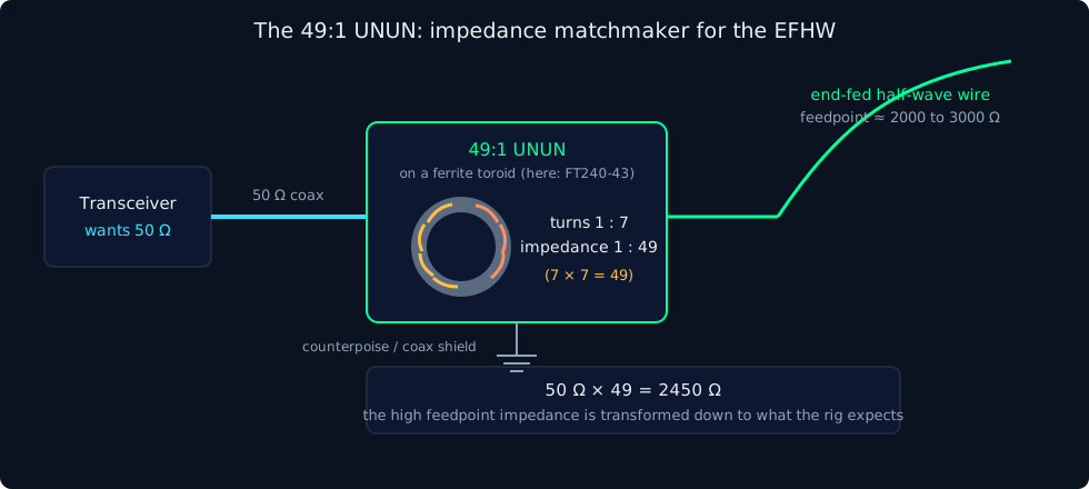
An end-fed half-wave antenna is popular for a simple reason: you feed it at the end, so you only need one support point. But that convenience comes with a catch. At the end of a half-wave wire the impedance is very high, somewhere around 2000 to 3000 ohms depending on the installation. Your transceiver and coax want 50 ohms.
That is the UNUN’s job (UNUN means unbalanced to unbalanced). It is a transformer: impedance transforms with the square of the turns ratio, so a 7:1 turns ratio gives a 49:1 impedance ratio, and 2450 divided by 49 lands neatly on 50 ohms.
The build and the bench test
ON4BB wound his UNUN on an FT240-43 core. His honest reason for that choice: he had one lying around. It happens to be an excellent choice too, as we will see. FT240 is the large 2.4 inch size, and 43 is the ferrite material mix. Big core, popular mix, the combination you will find in most commercial EFHW transformers.
To test it without hanging a wire in the air, he terminated the output with a metal film resistor of about 2500 ohms, a dummy stand-in for the EFHW feedpoint, and swept it with a DG8SAQ VNWA from 3 to 28.8 MHz using roughly 2000 measurement points. A small compensation capacitance across the input flattens the response at the high end of HF, a common trick in these designs.
The results:
| Band | Frequency | Measured Z | VSWR |
|---|---|---|---|
| 80 m | 3.58 MHz | 40.4 Ω | 1.76 |
| 40 m | 7.06 MHz | 44.1 Ω | 1.30 |
| 20 m | 14.30 MHz | 42.9 Ω | 1.18 |
| 17 m | 18.11 MHz | 43.1 Ω | 1.19 |
| 15 m | 21.13 MHz | 47.5 Ω | 1.24 |
| 10 m | 28.80 MHz | 79.1 Ω | 1.58 |
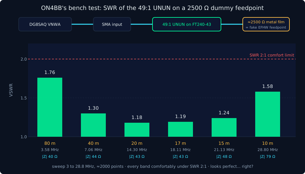
Everything under 2:1. The real part of the impedance tracked the magnitude closely, meaning very little reactive component, and the whole Smith chart trace stayed inside the 2:1 circle, running slightly inductive. On 17 m and 12 m the SWR sat around 1.2. A textbook result.
The question that started the rabbit hole
Looking at those curves, I got curious about something, and purely out of curiosity I asked it in the chat: does a low SWR actually prove the transformer is good? I had read somewhere that a VNA only looks at what comes back. Power that does not reflect is not necessarily radiated. Part of it can simply stay behind as heat in the core.
ON4BB’s answer was refreshingly direct: correct. The VSWR is a value computed from the real and complex components of the reflection. Core losses are not measured here at all. The SWR curve tells you how the transformer behaves as a match across frequency. Nothing more.
Here is the thought experiment that made it click for me. A dummy load has a perfect SWR of 1:1 and radiates exactly nothing. Absorption looks identical to a good match, because from the meter’s point of view it is a good match. A lossy ferrite core can actually make your SWR curve look better while quietly eating your signal.
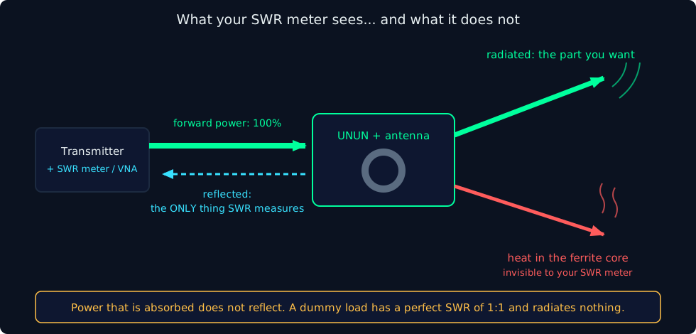
So a low SWR is a necessary condition, but not a sufficient one. To measure the real loss you need a transmission measurement (S21), typically done by building two identical transformers back to back: 50 ohms in, up to 2450 ohms, straight back down to 50 ohms. Measure the total insertion loss, divide by two, and you finally know what one transformer costs you.
Meet mix 43: a material with two personalities
This is where ON4AOL steered the discussion toward the datasheets, and where it gets properly interesting.
Ferrite is not one thing. Manufacturers blend different chemistries for different frequency ranges. The two big families are MnZn (manganese zinc) for lower frequencies and NiZn (nickel zinc) for higher frequencies. Mix 43 is a NiZn material.
A ferrite’s behaviour is described by its complex permeability, which has two parts. The real part, written μ′, is the useful part: it multiplies the inductance of your winding, which is why a few turns on a toroid can do the work of a huge air-cored coil. The imaginary part, μ″, is the loss: energy converted directly into heat inside the core.
Now look at what Fair-Rite’s own measured data for mix 43 shows across the HF range:
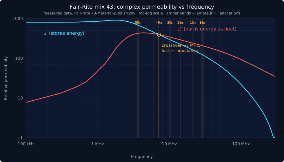
| Frequency | μ′ (useful) | μ″ (loss) | Ratio |
|---|---|---|---|
| 1 MHz | 851 | 48 | 0.06 |
| 3.5 MHz | 708 | 418 | 0.59 |
| 7 MHz | 394 | 394 | 1.00 |
| 14 MHz | 226 | 293 | 1.29 |
| 28 MHz | 127 | 211 | 1.66 |
Read that middle row again. At 7 MHz, right on the 40 m band, the loss part equals the useful part. Above that, mix 43 is more loss than inductance. The loss peak sits around 4 to 5 MHz, squarely in the low HF bands.
A helpful rule of thumb from a video ON4AOL shared (comparing Ferroxcube’s MnZn material 3B1 with NiZn material 4B1 for ferrite rod antennas): look at the distance between the μ′ and μ″ curves on a log scale. The bigger the gap, the lower the relative loss at that frequency. For mix 43 that gap closes rapidly through the HF range.
And temperature stacks on top of this. Fair-Rite’s data shows the permeability of mix 43 rising with temperature to a peak near 155 °C, then collapsing at the Curie point around 180 °C. Above 25 MHz the core’s impedance also derates as it warms up. A hot core is a different component than a cold one: the match shifts, SWR starts moving, and your amplifier gets stressed. Heat also feeds on itself, since losses change further as temperature climbs.
So is mix 43 a bad choice? No. Here is the twist
If μ″ is “loss”, why does anyone use 43 above 7 MHz? Because loss is not always the enemy. It depends entirely on what job you give the core.
A common-mode choke exists to block unwanted current flowing on the outside of your coax. For that job, loss is a feature: the choke turns common-mode RF into a little bit of heat instead of letting it radiate from your feedline into your shack. A material that is “too good” (low loss, like mix 61 at HF) makes a poor HF choke.
A transformer, on the other hand, wants to pass power through as efficiently as possible. There, μ″ is a genuine cost, paid as heat in the core.
Same physics, opposite verdicts. This is why published frequency ranges for ferrite mixes seem to contradict each other: one table says mix 43 is fine from 1 to 50 MHz, another says 5 to 20 MHz for EFHW transformers. Both can be right, because they describe different jobs, different winding styles, and different power levels. The Mini Ring Core Calculator makes the same distinction for the FT240-43: usable as a resonant inductor only up to about 1 MHz, wideband transformer duty from 1 to 50 MHz, choke duty from 30 to 600 MHz. And as ON4AOL pointed out, the wideband rating assumes transmission-line style winding, where tightly coupled parallel conductors carry the field instead of pushing all the flux through the core.
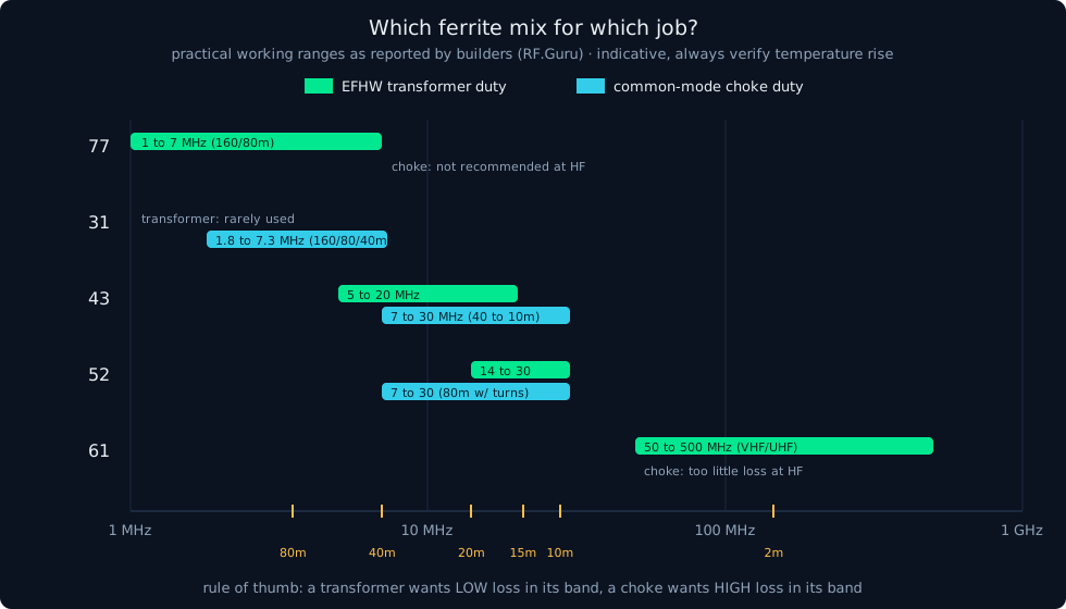
Practical EFHW transformer guidance reported by experienced builders (RF.Guru): mix 77 for 160/80 m, mix 43 for roughly 5 to 20 MHz (40 m is borderline depending on power and duty cycle, and it runs warm on 80 m), mix 52 for 14 to 30 MHz at power. For common-mode chokes: mix 31 is the workhorse on 160/80/40 m, with 31 or 52 covering 40 through 10 m, and 43 mostly above 7 MHz.
What this means at real power levels
Everything above was measured at VNA signal levels, milliwatts. Crank up the power and the loss story becomes a thermal story.
The numbers get big quickly. One example from the RF.Guru article: 2 A of common-mode current dissipating in a choke means roughly 8 W of heat at 100 W transmit power. At higher power with more common-mode current you can exceed 60 W of heat, enough to cook a small core. Sustained duty-cycle modes like FT8 are much harder on a core than SSB. A sealed weatherproof box in the sun makes it worse again.
This is also why clip-on and sleeve ferrites do not belong in a high-power signal path. Split cores have air gaps, so coupling is loose and impedance per piece is low, and their small cross-section has almost no thermal mass. They are great for cleaning up RFI on USB and control cables, and that is where they should stay.
The practical checklist I took away:
- Pick the mix for the job (transformer versus choke) and the bands. Although as ON4BB proves, sometimes the junk box holds exactly the right core.
- Bigger cores run cooler: more cross-section means more thermal mass and lower flux density per ampere-turn. FT240 or stacked cores for 100 W and up.
- Use heat as your instrument. After a long transmission, feel the core (carefully). The RF.Guru rule: if you cannot keep a finger on it for 2 seconds, you are in the danger zone. Repeated overheating permanently degrades ferrite.
- A low SWR that slowly drifts during transmission is a classic hint that a core is heating up.
- Want the real number? Build two, measure back to back with S21, divide by two.
Takeaways for fellow beginners
The SWR meter is the first instrument every ham learns to read, and it is genuinely useful. But it answers exactly one question: how much power came back. It says nothing about where the rest went. ON4BB’s UNUN measures beautifully as a match, and mix 43 on a big FT240 core is a sensible, proven recipe for an EFHW at typical power levels. What this deep dive gave me personally: I started out knowing next to nothing about ferrite, had picked up bits and pieces here and there, and by looking it up and reading along I now understand what the curve does and does not prove, and how the rest could be measured. That is exactly what a club chat is for.
Credits and sources
Thanks to Luc ON4BB for the build, the measurements and the answers, and to Luc ON4AOL for pushing the discussion into the datasheets. This is what a club is for.
- Fair-Rite 43 material datasheet: fair-rite.com/43-material-data-sheet
- Fair-Rite measured complex permeability data for 43 material (43-Material-publish.csv)
- RF.Guru: Why Your Ferrite Might Be Cooking Alive
- RF.Guru: Sleeved and Clip-On Ferrites Are Not for QRO
- Video: Ferrite rod antennas for shortwave, MnZn versus NiZn materials
- Jack R. Smith K8ZOA, “Observations on Ferrite Rod Antennas”, QEX July/August 2008
- Dan McGillis, “Calculating the Inductance of a Ferrite Rod-Cored Coil and Selecting a Wire Size” (12/06)
- Mini Ring Core Calculator (FT240-43 frequency range classification)
Frequency ranges for ferrite mixes are indicative and depend on winding style, turns count, power and duty cycle. When in doubt: measure, and mind the temperature.