This was the first proper dry run of my portable setup: a QRP Labs QMX running 5 watts, a SOTAbeams Band Hopper IV linked dipole on a 7 metre mast, and an external LiTime battery feeding the radio through a buck converter that keeps everything safely under 12 volts. No contacts logged yet, this was purely about building it, powering it, and seeing whether the whole chain behaves.
Why QRP, and why now
My home station is an IC-7300 MkII into a vertical, and as a Belgian Class C operator I am allowed 25 watts on HF. That is already modest by most standards. So the obvious question is: why deliberately drop to 5 watts?
Two reasons. First, portable operating is where I want to spend my summer evenings, and 5 watts means a tiny radio, a small battery, and a pack that I can carry on a bike or on foot without thinking about it. Second, QRP is a brilliant teacher. With 5 watts there is nowhere to hide. Antenna height, feedline losses, common mode current, band choice and propagation all show up immediately in your results. If something in the chain is mediocre, you will know.
This post documents the build itself. The on-air results come later.
The station schematic
Before the individual parts, here is the whole thing as one drawing. Three signal types run through this station and it helps to keep them separate in your head: DC power in amber, RF in green, and audio and data in cyan.
Worth pointing out: there is no external sound card and no separate CAT interface. The QMX contains a 24-bit USB sound card and a virtual COM port, so a single USB-C cable carries audio in both directions plus rig control. For FT8 that is the whole interface.
The radio: QRP Labs QMX
The QMX is a five band (80, 60, 40, 30 and 20 m) multimode transceiver from QRP Labs. It is an embedded SDR in a box about the size of a pack of cards, weighing 220 grams including the enclosure, and it does CW, digital modes and SSB.
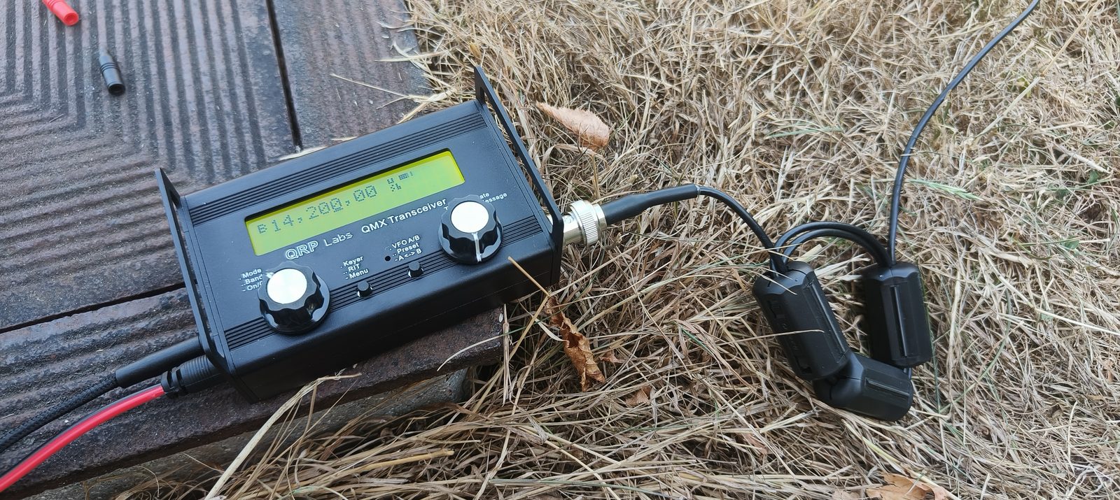
A few things that make it a natural fit for portable work:
- Very low receive current, around 80 mA. My bench meter showed 0.09 A at 11.50 V, so roughly one watt of total consumption while listening.
- Built in SWR bridge, so I can check the antenna without carrying an extra meter.
- USB-C for CAT control and audio, which will matter once I start logging and running digital modes from a laptop or tablet.
- Solid state transmit and receive switching, so break-in CW is clean and silent.
For SSB I added a G7UFO Turret Mini Microphone, a compact assembled mic built around the same electret element that QRP Labs recommends for the QMX SSB firmware. It weighs about 20 grams and disappears into a pocket of the bag. For a radio this small, a full sized hand microphone would look faintly ridiculous.
The part I care most about: staying under 12 volts
This is the detail I want any other new QMX owner to read carefully, because it is the easiest way to destroy the radio.
The QMX specification is a supply range of 6.0 to 12.0 volts. Not “around 12”. The final amplifier transistors are the limit, and pushing more voltage into them mostly buys you heat and risk. A nominal 12 volt LiFePO4 pack is exactly the trap here: mine sits comfortably above 13 volts when it is freshly charged, which is well outside the safe window.
So the battery never touches the radio directly. In between sits an adjustable DC-DC buck converter with a display, set to 11.50 volts. That number is not arbitrary: it matches the default value of the QMX firmware’s own “Max PA voltage” protection setting, which was added specifically to protect the finals from exactly this mistake.
The BMS inside the LiTime pack is worth a word too, because it is easy to assume it does more than it does. The BMS protects the battery: it cuts off on over-discharge, over-charge, over-current and temperature. It does nothing at all to protect your radio from the pack’s normal working voltage. Regulation down to 11.50 V is a separate job, and that is the converter’s job.
Powerpole everywhere
Every DC connection in this station is an Anderson Powerpole. Battery to converter, converter to radio, and the spare tails for accessories. It is a small standardisation decision that pays off constantly:
- Nothing can be connected the wrong way round.
- Any part of the chain can be swapped in the field without tools.
- The club and the wider hobby use the same standard, so borrowing or lending a power lead just works.
Building a portable station is the perfect moment to make that choice, before you have accumulated a drawer full of incompatible barrel plugs.
The antenna: SOTAbeams Band Hopper IV
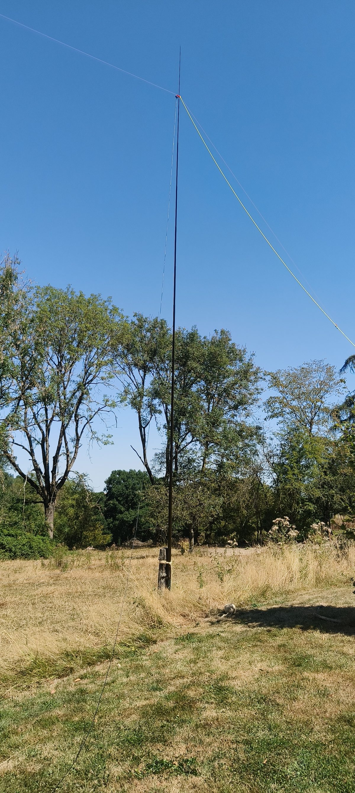
The Band Hopper IV is a linked dipole covering 20, 30, 40 and 80 metres. It is not a loaded compromise antenna: on each band you get a genuine full size half wave dipole, and there is no lossy matching network, so the power goes into the wire instead of into a coil.
The whole thing is about 48 metres end to end on 80 m, comes pre-tuned, includes a ferrite core current balun in the centrepiece, and ships with a 10 metre RG174 feeder terminated in BNC, three wire winders, a back guy and pegs. The package weighs well under half a kilogram. It is rated for 125 watts, which for a 5 watt radio is a comfortable margin of about 14 dB.
How the links actually work
A linked dipole is a dipole cut for the highest band, with extra wire sections added on for each lower band. Between the sections sit small insulators with crocodile clips: the links. Close a link and the next section is electrically joined on, making the antenna longer and moving it down in frequency. Open it and everything beyond that point is disconnected and simply hangs, or gets wound back on its wire winder.
Which links closed for which band
| Band | L1 (nearest centre) | L2 | L3 | L4 (80 m trim) |
|---|---|---|---|---|
| 20 m | open | open | open | no effect |
| 30 m | closed | open | open | no effect |
| 40 m | closed | closed | open | no effect |
| 80 m | closed | closed | closed | sets where in the band you are |
The logic is simple once you see it: to go one band lower, you close one more link, working outwards from the centre. The highest band uses the shortest wire, so all links open. The lowest band uses everything, so all links closed.
And the extra 80 m link at the far end? That one is not a band selector at all. The Band Hopper IV covers 3.5 to 3.7 MHz with a 1.5:1 SWR bandwidth using the SOTAbeams “Hopper Jump” arrangement, and that last link is the trimming mechanism: it moves the resonance within 80 m rather than to another band. So it decides whether you are best matched near the CW end or nearer the SSB end, and on 20, 30 and 40 m it does nothing whatsoever, because it sits beyond an open link and is electrically disconnected from the antenna.
Points to watch when setting up
These are the things I want to have internalised before I care about contacts. Most of them are the kind of mistake that costs you an hour in a field.
- The same links closed on both legs. This is the number one error with linked dipoles. Two closed on the left and one closed on the right is not a 40 m antenna, it is an off centre fed wire with a bad SWR and a lot of current on the outside of your coax. Count them, out loud, on both sides.
- Walk one leg, then the other, then check again. Change bands on one side, walk to the other end, change it, then walk back past the first one to confirm. It takes two minutes and it removes all doubt.
- Check the clips are biting wire, not insulation. A crocodile clip that looks closed but is gripping the plastic gives you an intermittent antenna. Reviews of these antennas also mention the clips corroding over time, so a quick clean of the contact surfaces belongs in the maintenance routine.
- Keep the ends up and out of reach. The ends of a dipole are the high voltage points. It is only 5 watts, but the ends should still be above head height, clear of vegetation and out of the way of anyone walking past. Wet grass touching the ends will also pull your resonance around.
- Tension both legs equally. On this setup the two dipole legs are also two of the three guys for the mast. Uneven tension bends the mast and makes the pattern asymmetric.
- The centre slides to the right height. The centrepiece belongs at the junction between the top sections, not right at the tip. The thin top section will not hold the weight, and the antenna does not work properly if it is too high on a tapered pole.
- Sweep the SWR after every band change, before transmitting. The QMX has the tool built in. It takes ten seconds and it catches an open link, a bad clip or a leg that has fallen into a bush.
- Space check before you commit. 80 m is roughly 48 metres end to end. Choose the site with the lowest band you intend to use in mind, not the highest.
Points to watch with the transceiver
- Supply voltage, every single time. 6.0 to 12.0 V. Confirm the converter output on its own display before plugging into the radio, and check that the QMX "Max PA voltage" protection setting is where you expect it. Enable the battery voltage indicator on the LCD so the supply is visible while operating.
- Never transmit without an antenna or dummy load. The QMX has SWR protection, and it works, but designing your routine around a safety net is how safety nets get tested.
- Band configuration must match your hardware version. The QMX exists in several band variants. If the firmware band configuration does not match the filters actually fitted, output and receive sensitivity will be wrong on some bands. Mine is the 80 to 20 m version, which pairs neatly with the Band Hopper IV.
- Keep the firmware current. The PA voltage protection, the SWR tools and much of the SSB behaviour arrived in firmware updates. Update at home over USB, not in a field.
- Do not swap antennas or bands while keyed. Obvious, easy to do by accident when the radio is on the ground and you are holding a mic.
- Duty cycle and heat. Digital modes transmit at full power for the whole slot. A small aluminium box in direct sunlight running FT8 back to back gets warm. Keep it shaded and give it gaps.
- Watch the USB side. A laptop connected by USB shares a ground with the radio, and that connection can carry RF back into the audio chain. Short cable, ferrites on the coax, and if strange things happen on transmit, suspect common mode before you suspect the software.
- Set the microphone level deliberately. The QMX has mic gain, equalisation and compression settings for SSB. Too much gain on a 5 watt signal makes you harder to copy, not louder. Set it once, at home, and leave it.
- Use practice mode for testing. The QMX can go through the motions without radiating, which is exactly what you want while learning the menus.
- Enable the SWR cutout in software too. "Halt Tx when SWR is above 2.5" in WSJT-X, on top of the QMX's own sweep before the first transmission on every band.
- Poll fast enough to keep up with yourself. Two to three seconds, not the default ten, so the software never lags a band change made on the radio.
- Do not take a release candidate into a field. Revert Hamlib to the last stable version before an activation, or test the candidate at home first.
- Check the callsign and grid in the title bar before transmitting. A wrong grid is a silent error: everything works, and every distance and every confirmation is simply wrong.
Extra ferrites on the feedline
The Band Hopper already has a proper ferrite core balun at the feedpoint, so this is belt and braces rather than a fix for a known problem. I added clip-on ferrite cores at the radio end of the RG174, with the thin coax wound through each core several times.
The reason is common mode current: RF flowing back along the outside of the coax braid instead of staying in the antenna. On a portable setup that shows up as extra received noise, RF finding its way into the radio or the laptop, and an antenna pattern that includes your feedline. The thin RG174 is a gift here, because it will take several turns through a small snap-on core where thicker coax would only manage one pass. More turns means much more choking impedance.
Is it strictly necessary? Probably not with the built in balun. Does it cost about 10 euros and 30 grams? Yes. On a station where every dB matters, that trade is easy.
Labelling: the boring thing that saves the day
This deserves its own heading, because in a field, at dusk, with cold hands, memory is not a reliable band selector.
- Label every link with its band. A small piece of tape or a printed heatshrink sleeve on each insulator: L1, L2, L3 and the band it enables. Ideally colour code them so left and right match at a glance.
- Label both ends of the coax and the antenna bag itself, so the right feeder ends up with the right antenna.
- Label the Powerpole leads: battery side, converter input, converter output. Write “11.5 V MAX” on the converter output lead. That single label is the cheapest insurance policy in the whole station.
- Put a card in the bag. A laminated card with the band and link table, the trim link answer once I have measured it, and the start up order: check converter output, connect radio, check SWR, then transmit.
Everything on that list costs a few minutes at the kitchen table and prevents the kind of error that only reveals itself as a mysterious high SWR when you are already set up.
Setting up WSJT-X for the portable station
The other half of a portable station is the software, and it deserves its own configuration rather than a handful of settings changed by hand each time. WSJT-X can clone a configuration, so the shack setup stays untouched and a separate Portable profile carries the callsign, the grid and the radio settings for the QMX.
The QMX needs no interface hardware at all. One USB-C cable carries CAT control, transmit audio and receive audio. The Hamlib entry is QRPLabs QMX, PTT method is CAT, and the serial parameters are the ordinary 8 data bits, 1 stop bit, no handshake. The baud rate is nominal, because the port is a virtual USB serial device rather than a real line. The COM port will not be the one the shack radio uses, so it is worth checking rather than assuming.
Two settings matter more than the rest here:
- Poll interval. The default of 10 seconds suits a station that sits on one band all evening. Portable operating is the opposite, and with a slow poll, WSJT-X can be up to ten seconds behind after a band change made on the radio. That is precisely the window in which a transmission goes out on the wrong dial frequency. Two to three seconds closes it.
- Halt Tx when SWR is above 2.5. With a linked dipole, a forgotten link means a badly mismatched antenna, and the QMX has no ATU to hide behind. This one checkbox stops the transmission before the PA has to deal with it. It sits alongside the manual SWR sweep rather than replacing it.
Two settings worth testing rather than trusting. The WSJT-X defaults for Mode and Split Operation were designed around conventional SSB radios. The point of split is to keep the transmit audio between 1500 and 2000 Hz so that audio harmonics cannot pass through the transmit sideband filter. The QMX does not work that way: it measures the frequency of the incoming audio tone and synthesises the RF directly, so there is no sideband filter for harmonics to slip past. The defaults may work perfectly well, but if the radio drops out of digital mode on transmit, set Mode to None, and if VFO B misbehaves, switch Split to Fake It.
And one that answers my actual question. On the Reporting tab there is an option to spot to PSK Reporter. This is the cheapest reach measurement a QRP station has, and it needs no contacts whatsoever. Call CQ, and within a few minutes pskreporter.info shows every station that decoded the signal, with distance and report, whether or not anybody came back. For a brand new antenna that is exactly the right question: not “did someone answer”, but “where is this station actually being heard”. It also separates two problems that feel identical from the operating position, namely nobody hearing you and nobody replying.
Two settings that decide whether the station runs by itself. Auto Seq should stay on. It is what steps the messages through a QSO, and it is what lets WSJT-X keep calling CQ between contacts without a click. The setting that trips people up is “Disable Tx after sending 73” on the General tab: leave that checked and transmission simply stops after every contact, so each new CQ has to be started by hand. Unchecked, WSJT-X moves on to the CQ message and carries on. Worth knowing alongside it: the Tx Watchdog, six minutes by default, deliberately stops transmission if the operator has not touched anything for that long. If CQ calling dies during a quiet spell, that is usually why, and it is a safety feature rather than a fault.
There is one exception to leaving Auto Seq alone. If you want to send a custom free-text message instead of the standard 73, say a WWFF reference for a hunter who asked for it on air, Auto Seq will overwrite whatever you typed on the next decode. The only way through is to type it when the QSO has actually reached the 73 stage, untick Auto Seq for that single transmission, let it go out, and tick it straight back on. Forgetting that last step is the classic error, because sequencing then stops working for the rest of the session without saying so.
One more thing that belongs in a field kit rather than a settings dialog: WSJT-X can update Hamlib from inside its own Radio tab, and a version string ending in “rc” is a release candidate. It may well fix something specific, but an activation is not the place to discover what else it changed.
First power up in the field
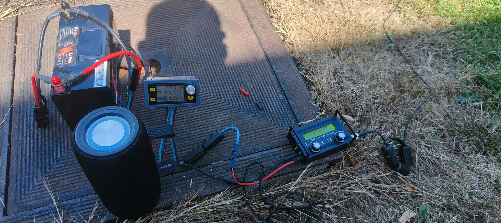
Everything did what it was supposed to. The converter held 11.50 volts, the QMX drew about 90 mA on receive, the noise floor out in the field was dramatically lower than at home, and 40 metres was full of signals in the late afternoon. I tuned around on 20 m and 40 m for a while, listened to how the band sounded through the small speaker, and mostly grinned at the fact that this entire station fits in one bag.
What it costs, roughly
| Item | Order of magnitude |
|---|---|
| QRP Labs QMX, assembled, with enclosure | ~ 175 EUR |
| SOTAbeams Band Hopper IV | ~ 80 EUR |
| SOTAbeams Tactical 7000hds mast | ~ 75 EUR |
| LiTime 12 V 20 Ah LiFePO4 | ~ 60 EUR |
| G7UFO Turret Mini Microphone | ~ 30 EUR |
| Anderson Powerpole set and crimp tool | ~ 30 EUR |
| DC-DC buck converter | ~ 25 EUR |
| Bluetooth speaker (optional) | ~ 25 EUR |
| Clip-on ferrite cores | ~ 10 EUR |
| Total | roughly 500 EUR |
Two observations on that number. First, the QMX is noticeably cheaper as a kit than assembled, so a builder can shave a good chunk off and learn a lot in the process. Second, roughly a third of the total is antenna and mast, and that is money well spent. A better radio behind a poor antenna is a bad trade, especially at 5 watts.
Weight and pack size
The numbers that actually decide whether a station gets used:
| Item | Weight |
|---|---|
| QMX including enclosure | 220 g |
| Band Hopper IV complete | under 475 g |
| Microphone | 20 g |
| Battery, converter, cabling | the bulk of it |
The radio, antenna and microphone together come in at well under a kilogram. The battery dominates, and that is the obvious place to optimise later: a smaller LiFePO4 pack or a USB-PD power bank with a 12 volt trigger cable would cut the load significantly, since a 5 watt radio drawing under a fifth of an amp on receive does not need 20 Ah to fill an afternoon.
What comes next
This was a build and shakedown, nothing more. No QSOs were logged, deliberately. The next steps are already lined up:
- First portable contacts. Getting the callsign out on 40 m and 20 m and finding out what 5 watts into an inverted V actually achieves from JO21EE.
- Making the range visible. Every contact goes into the logbook on this site, and the map with its great circle arcs will show exactly how far this station reaches. I am genuinely curious how the QRP arcs compare with the 25 watt home station arcs.
- A first PSK Reporter map. Call CQ on 40 m and 20 m and let the reception reports draw the coverage, before a single contact is in the log.
- Running the portable logging setup for real. The configurations are built and written up in the portable manual. What remains is using them under field conditions and finding out which steps I forget.
- Measuring the 80 m trim link and writing the result on the card in the antenna bag.
There is something appealing about the fact that this is roughly how amateur radio started: a wire between two supports, a small box, and a battery. Everything else is refinement.
More soon, once the log has some entries in it.
Everything in this post that has to happen in a fixed order, on one printable sheet: the 11.50 V supply check, the link symmetry rule, the SWR sweep after every band change, and the WSJT-X settings.
73 de ON3VZ